Hey all,
I've had a few requests for Arduino code to run the ADF4351 (also ADF4350) from an Arduino.
What I am posting is code that I received from Richard – OE6OCG a year or two back. He set it up to use with an LCD and 4 button controller. For my use I modified it to use a rotary encoder, TFT touch display, and some other additions, but that's for another post and not included here. This is exactly as I received it.
If you would like to see cetain features added to this code leave me a comment, send me an email, or get me on twitter @kd0cq.
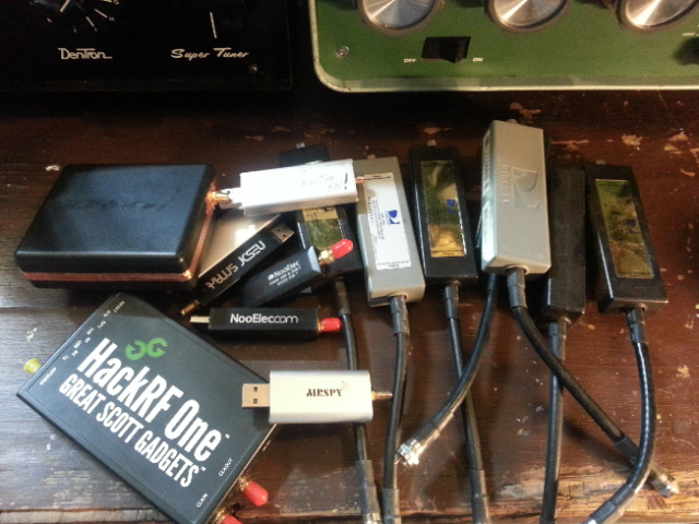
I cobbled together the ADF4351 and an Analog Devices RF Detector Surf Board kit and made a microwave SNA of sorts. The eval board has 3 devices on it, ADL5902, ADL5513, and ADL5511 and only cost $5+ship! lol can't beat that for an eval board. I think they still have some left at that price. Check www.richardsonrfpd.com (a division of ARROW) Part # ADL5XDETECTRKIT
Whenever I find the files for that again I'll post them as well.
I'm also providing a download link as the Code display on this theme sucks.
If you use the code below please send Richard a few dollars for beer money or radio toys!
CLICK TO DOWNLOAD ~4KB
//
//*****************************************************************
// ADF4351 PLL-Synthesizer 33Mhz - 4,4Ghz
// Integer mode Demo OE6OCG 1/2015
// Hardware Arduino Uno mit Adafruit Keyb-LCD Shield 16x2 ~ 10USD
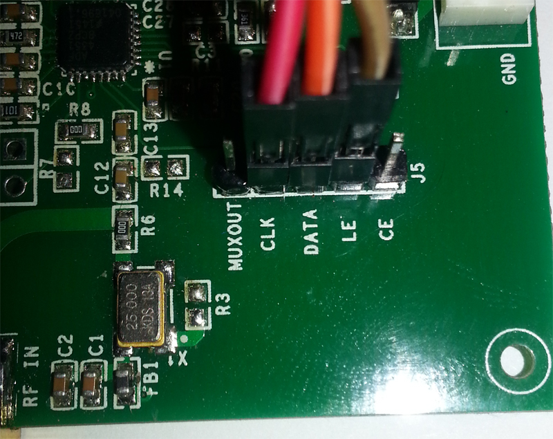
// ADF4351 PLL-VCO Board assembled from Ebay or China ~ 40 USD
//
// Buttoms:
// up/down = Freq +- with stepsize
// left = frequency step's from 6.25khz to 1Mhz
// right = scan with stepsize
// select = predefined startfrequencies from 34Mhz to 4.4 Ghz
//
// IDE: Arduino 1.5.4 or up without spec. Library
// License: Free or a gift to Paypal oe6ocg@aon.at
//*****************************************************************
/* Hardware connection Uno to PLL-Board (3.3V logic)
+-----+
+----[PWR]-------------------| USB |--+
| +-----+ | output: 33Mhz - 4.4Ghz ~ 3 dbm
| GND/RST2 [ ][ ] | PLL-Board + Arduino with Display Bk.light draw 200mA on 5V USB
| MOSI2/SCK2 [ ][ ] A5/SCL[ ] | #
| 5V/MISO2 [ ][ ] A4/SDA[ ] | |---|_3.3k_|-----\ |
| AREF[ ] | !---|_3.3k_|---\ | _____|______
| GND[ ] |----!---|_3.3k_|-| | | | |
| [ ]N/C SCK/13[ ] |------|_1.5k_|---!-|-|----Clock--|ADF4351 |
| [ ]v.ref MISO/12[ ] | | | |PLL Board |
| [ ]RST MOSI/11[ ]~|------|_1.5k_|-----!-|----Data---|3.3V logic |
| [ ]3V3 +---+ 10[ ]~| | | |
| [ ]5v | A | 9[ ]~| LCD !----LE-----| |
| [ ]GND -| R |- 8[ ] | LCD | |____________|
| [ ]GND -| D |- | |
| [ ]Vin -| U |- 7[ ] | LCD |
| -| I |- 6[ ]~| LCD |
Keyb | [ ]A0 -| N |- 5[ ]~| LCD |
RSSI | [ ]A1 -| O |- 4[ ] | LCD |
| [ ]A2 +---+ INT1/3[ ]~|------|_1.5k_|---LE--/
| [ ]A3 INT0/2[ ] |
| [ ]A4/SDA RST SCK MISO TX>1[ ] |
| [ ]A5/SCL [ ] [ ] [ ] RX<0[ ] |
| [ ] [ ] [ ] |
| UNO GND MOSI 5V ____________/
\_______________________/
*/
#include <Wire.h>
#include <LiquidCrystal.h>
#include <SPI.h>
LiquidCrystal lcd(8, 9, 4, 5, 6, 7); //DFR LCD-keyb Shield
const int slaveSelectPin = 3; //SPI-SS bzw. enable ADF4350
long Freq = 44220000; //Startfrequenz generel 100Hz aulösung
long refin = 2500000; // Refrenquarz = 25Mhz
long ChanStep = 625; //Kanalraster = 6,25Khz kleinstes raster
long channel[13]; // Kanal-speicher
long Step[5]; // Kanalraster-speicher
int CHnum = 0; // eingestellter Kanal
int StepNum = 0; // eingestelltes Kanalraster
unsigned long Reg[6]; //ADF4351 Reg's
byte tenHz, hundredHz, ones, tens, hundreds, thousands, tenthousands, hundredthousands, millions;
int lcd_key = 0;
int adc_key_in = 0;
#define btnRIGHT 0
#define btnUP 1
#define btnDOWN 2
#define btnLEFT 3
#define btnSELECT 4
#define btnNONE 5
void setup() {
lcd.begin(16, 2);
lcd.setCursor(0, 0);
lcd.print(" ADF4350 OE6OCG");
// Serial.begin(115200);// USB to PC for Debug only
pinMode (slaveSelectPin, OUTPUT);
digitalWrite(slaveSelectPin, LOW);
SPI.setDataMode(SPI_MODE0);
SPI.setBitOrder(MSBFIRST);
SPI.setClockDivider(SPI_CLOCK_DIV128);
SPI.begin();
delay(500);
Step[0] = 625; // 6,25 khz, 5khz geht nicht im Int-N Mode(MOD > 4095) bei 25Mhz Ref.
Step[1] = 1000; // 10 khz
Step[2] = 1250; // 12.5 khz
Step[3] = 2500; // 25 khz
Step[4] = 100000; // 1 Mhz Step
channel[0] = 3400000; // Band select FIXFREQUENZEN
channel[1] = 5150000; //51.5 Mhz
channel[2] = 14455000;
channel[3] = 14500000;
channel[4] = 14560000;
channel[5] = 43000000;
channel[6] = 43127500;
channel[7] = 43887500;
channel[8] = 124500000;
channel[9] = 129820000;
channel[10] = 234500000;
channel[11] = 300000000;
channel[12] = 440000000; // 4.4Ghz
lcd.setCursor(0, 0);
lcd.print(" ");
lcd.setCursor(0, 0);
lcd.print("S=");
lcd.print(ChanStep);
lcd.print("0");
lcd.setCursor(12, 1);
lcd.print(" Mhz");// print Mhz
SetFreq(Freq);
}
void loop() {
lcd_key = read_LCD_buttons();
switch (lcd_key)
{
case btnRIGHT:
{ //Scannen +-10Mhz mit eingestellten Kanalraster
long FreqHi;
Freq = channel[CHnum];
if (ChanStep == 100000)
{
FreqHi = Freq + 10000000; // +100Mhz
}
else
{ FreqHi = Freq + 500000; // +5Mhz};
};
while (Freq < FreqHi) {
Freq += ChanStep;
SetFreq(Freq);
}
if (ChanStep == 100000)
{
FreqHi = FreqHi - 10000000; // -100Mhz
}
else
{ FreqHi = FreqHi - 500000; // -5Mhz};
};
while (FreqHi < Freq) {
Freq -= ChanStep;
SetFreq(Freq);
}
break;
}
case btnLEFT:
{
StepNum += 1;
if (StepNum > 4) StepNum = 0;
ChanStep = Step[StepNum];
lcd.setCursor(2, 0);
lcd.print(" ");
lcd.setCursor(2, 0);
lcd.print(ChanStep);
lcd.print("0");
// render Frequenz nach Raster
SetFreq(Freq);
delay(200);
break;
}
case btnUP:
{
Freq += ChanStep;
SetFreq(Freq);
break;
}
case btnDOWN:
{
Freq -= ChanStep;
SetFreq(Freq);
break;
}
case btnSELECT:
{
//lcd.print("SELECT");
CHnum += 1;
if (CHnum > 12) CHnum = 0;
Freq = channel[CHnum];
SetFreq(Freq);
delay(200);
break;
}
case btnNONE:
{
//lcd.print("NONE ");
break;
}
}
adc_key_in = analogRead(0); // verhindert scannen wenn taste zulange gedrückt wird
delay(20);
//Serial.print ("ADC="); Serial.print (adc_key_in); Serial.print ("\r\n");
while (adc_key_in < 900) {
adc_key_in = analogRead(0);
delay(20);
}
}
int read_LCD_buttons()
{
adc_key_in = analogRead(0);
if (adc_key_in > 1000) return btnNONE;
if (adc_key_in < 50) return btnRIGHT;
if (adc_key_in < 195) return btnUP;
if (adc_key_in < 380) return btnDOWN;
if (adc_key_in < 555) return btnLEFT;
if (adc_key_in < 790) return btnSELECT;
return btnNONE;
}
void SetFreq(long Freq)
{
// lcd.setCursor(0, 1); // Cursor auf 2.Zeile
// lcd.print(Freq);
// lcd.print(" Mhz ");
showFreq(Freq);
ConvertFreq(Freq, Reg);
WriteADF2(5);
delayMicroseconds(2500);
WriteADF2(4);
delayMicroseconds(2500);
WriteADF2(3);
delayMicroseconds(2500);
WriteADF2(2);
delayMicroseconds(2500);
WriteADF2(1);
delayMicroseconds(2500);
WriteADF2(0);
delayMicroseconds(2500);
}
void WriteADF2(int idx)
{ // make 4 byte from integer for SPI-Transfer
byte buf[4];
for (int i = 0; i < 4; i++)
buf[i] = (byte)(Reg[idx] >> (i * 8));
WriteADF(buf[3], buf[2], buf[1], buf[0]);
}
int WriteADF(byte a1, byte a2, byte a3, byte a4) {
// write over SPI to ADF4350
digitalWrite(slaveSelectPin, LOW);
delayMicroseconds(10);
SPI.transfer(a1);
SPI.transfer(a2);
SPI.transfer(a3);
SPI.transfer(a4);
Toggle();
}
int Toggle() {
digitalWrite(slaveSelectPin, HIGH);
delayMicroseconds(5);
digitalWrite(slaveSelectPin, LOW);
}
void ConvertFreq(long freq, unsigned long R[])
{
// PLL-Reg-R0 = 32bit
// Registerselect 3bit
// int F_Frac = 4; // 12bit
// int N_Int = 92; // 16bit
// reserved // 1bit
// PLL-Reg-R1 = 32bit
// Registerselect 3bit
//int M_Mod = 5; // 12bit
int P_Phase = 1; // 12bit bei 2x12bit hintereinander pow()-bug !!
int Prescal = 0; // 1bit geht nicht ???
int PhaseAdj = 0; // 1bit geht auch nicht ???
// reserved // 3bit
// PLL-Reg-R2 = 32bit
// Registerselect 3bit
int U1_CountRes = 0; // 1bit
int U2_Cp3state = 0; // 1bit
int U3_PwrDown = 0; // 1bit
int U4_PDpola = 1; // 1bit
int U5_LPD = 0; // 1bit
int U6_LPF = 1; // 1bit 1=Integer, 0=Frac not spported yet
int CP_ChgPump = 7; // 4bit
int D1_DoublBuf = 0; // 1bit
// int R_Counter = 1; // 10bit
// int RD1_Rdiv2 = 0; // 1bit
// int RD2refdoubl = 0; // 1bit
int M_Muxout = 0; // 3bit
int LoNoisSpur = 0; // 2bit
// reserved // 1bit
// PLL-Reg-R3 = 32bit
// Registerselect 3bit
int D_Clk_div = 150; // 12bit
int C_Clk_mode = 0; // 2bit
// reserved // 1bit
int F1_Csr = 0; // 1bit
// reserved // 2bit
int F2_ChgChan = 0; // 1bit
int F3_ADB = 0; // 1bit
int F4_BandSel = 0; // 1bit
// reserved // 8bit
// PLL-Reg-R4 = 32bit
// Registerselect 3bit
int D_out_PWR = 0 ; // 2bit
int D_RF_ena = 1; // 1bit
int D_auxOutPwr = 0; // 2bit
int D_auxOutEna = 0; // 1bit
int D_auxOutSel = 0; // 1bit
int D_MTLD = 0; // 1bit
int D_VcoPwrDown = 0; // 1bit 1=VCO off
// int B_BandSelClk = 200; // 8bit
int D_RfDivSel = 3; // 3bit 3=70cm 4=2m
int D_FeedBck = 1; // 1bit
// reserved // 8bit
// PLL-Reg-R5 = 32bit
// Registerselect // 3bit
// reserved // 16bit
// reserved 11 // 2bit
// reserved // 1bit
int D_LdPinMod = 1; // 2bit muss 1 sein
// reserved // 8bit
// Referenz Freg Calc
// long refin = 250000; // Refrenquarz = 25000000hz
int R_Counter = 1; // 10bit
int RD1_Rdiv2 = 0; // 1bit
int RD2refdoubl = 0; // 1bit
int B_BandSelClk = 200; // 8bit
// int F4_BandSel = 0; // 1bit
// int F4_BandSel = 10.0 * B_BandSelClk / PFDFreq;
long RFout = Freq; // VCO-Frequenz
// calc bandselect und RF-div
int outdiv = 1;
if (RFout >= 220000000) {
outdiv = 1;
D_RfDivSel = 0;
}
if (RFout < 220000000) {
outdiv = 2;
D_RfDivSel = 1;
}
if (RFout < 110000000) {
outdiv = 4;
D_RfDivSel = 2;
}
if (RFout < 55000000) {
outdiv = 8;
D_RfDivSel = 3;
}
if (RFout < 27500000) {
outdiv = 16;
D_RfDivSel = 4;
}
if (RFout < 13800000) {
outdiv = 32;
D_RfDivSel = 5;
}
if (RFout < 6900000) {
outdiv = 64;
D_RfDivSel = 6;
}
float PFDFreq = refin * ((1.0 + RD2refdoubl) / (R_Counter * (1.0 + RD1_Rdiv2))); //Referenzfrequenz
float N = ((RFout) * outdiv) / PFDFreq;
int N_Int = N;
long M_Mod = PFDFreq * (100000 / ChanStep) / 100000;
int F_Frac = round((N - N_Int) * M_Mod);
R[0] = (unsigned long)(0 + F_Frac * pow(2, 3) + N_Int * pow(2, 15));
R[1] = (unsigned long)(1 + M_Mod * pow(2, 3) + P_Phase * pow(2, 15) + Prescal * pow(2, 27) + PhaseAdj * pow(2, 28));
// R[1] = (R[1])+1; // Registerselect adjust ?? because unpossible 2x12bit in pow() funktion
R[2] = (unsigned long)(2 + U1_CountRes * pow(2, 3) + U2_Cp3state * pow(2, 4) + U3_PwrDown * pow(2, 5) + U4_PDpola * pow(2, 6) + U5_LPD * pow(2, 7) + U6_LPF * pow(2, 8) + CP_ChgPump * pow(2, 9) + D1_DoublBuf * pow(2, 13) + R_Counter * pow(2, 14) + RD1_Rdiv2 * pow(2, 24) + RD2refdoubl * pow(2, 25) + M_Muxout * pow(2, 26) + LoNoisSpur * pow(2, 29));
R[3] = (unsigned long)(3 + D_Clk_div * pow(2, 3) + C_Clk_mode * pow(2, 15) + 0 * pow(2, 17) + F1_Csr * pow(2, 18) + 0 * pow(2, 19) + F2_ChgChan * pow(2, 21) + F3_ADB * pow(2, 22) + F4_BandSel * pow(2, 23) + 0 * pow(2, 24));
R[4] = (unsigned long)(4 + D_out_PWR * pow(2, 3) + D_RF_ena * pow(2, 5) + D_auxOutPwr * pow(2, 6) + D_auxOutEna * pow(2, 8) + D_auxOutSel * pow(2, 9) + D_MTLD * pow(2, 10) + D_VcoPwrDown * pow(2, 11) + B_BandSelClk * pow(2, 12) + D_RfDivSel * pow(2, 20) + D_FeedBck * pow(2, 23));
R[5] = (unsigned long)(5 + 0 * pow(2, 3) + 3 * pow(2, 19) + 0 * pow(2, 21) + D_LdPinMod * pow(2, 22));
}
//to do instead of writing 0x08000000 you can use other two possibilities: (1ul << 27) or (uint32_t) (1 << 27).
void showFreq(long FREQ) {
millions = int(FREQ / 100000000);
hundredthousands = ((FREQ / 10000000) % 10);
tenthousands = ((FREQ / 1000000) % 10);
thousands = ((FREQ / 100000) % 10);
hundreds = ((FREQ / 10000) % 10);
tens = ((FREQ / 1000) % 10);
ones = ((FREQ / 100) % 10);
hundredHz = ((FREQ / 10) % 10);
tenHz = ((FREQ) % 10);
lcd.setCursor(0, 1);
lcd.print(" ");
if (millions > 0) {
lcd.setCursor(0, 1);
lcd.print(millions);
lcd.print(".");
}
else {
lcd.setCursor(2, 1);
}
lcd.print(hundredthousands);
lcd.print(tenthousands);
lcd.print(thousands);
lcd.print(",");
lcd.print(hundreds);
lcd.print(tens);
lcd.print(ones);
lcd.print(".");
lcd.print(hundredHz);
lcd.print(tenHz);
};
// as PLL-Register Referenz
// R[0] = (0x002E0020); // 145.0 Mhz, 12.5khz raster
// R[1] = (0x08008029);
// R[2] = (0x00004E42);
// R[3] = (0x000004B3);
// R[4] = (0x00BC8024);
// R[5] = (0x00580005);
Hi
I have done some testing with the arduino soft of OE60CG which you also used and modified and I came on a problem of transfer of bits, the clock sends well the 32bits but the DATA send only 24bits, to test you can Send R [5] = (unsigned long) (5 + 268435455 * pow (2, 3)); On the R5 this corresponds to 28bits + the 3 bits of register selection, I have not yet found the problem but I think you also have this worry, everything works if you do not use the last 8 bits
73 f4fdw
thanks, ported to PIC and improved 🙂
Hello! Your project on ADF 4351 was very interested. It would be great if arduino supported the “sweep” function. Could you organize this function? In order for the frequency limits, width, delay time to be selected on the screen … I would like to change the frequency with the minimum delay and maximum speed. Is it possible to do this?
So, I found some issue with the code … I found that some frequencies from the ADF4351 worked just fine (2GHz for example) but other, such as 2.175GHz did not, even though it is an integer relationship to 25MHz reference … in the end, I pasted in the register values direct from the AD software, and it worked perfectly, but using the ConvertFreq() routine in the software produced some strange results.
What is also strange/undocumented is why the reference frequencies in the code above are the actual frequencies/10 eg “2500000” for 25MHz, not “25000000” ..
CODE IS WRONG – IT CONTINUES CHANGES FREQ OVER 4400 MHZ.