In Part 1 I showed that a cheap satellite upconverter can be used as a microwave downconverter with some mods. In this post I’ll show you the modifications needed, step-by-step tutorial style, and make lame jokes. After more experimentation and burned fingers today I’ve found a more efficient way to do the mod that provides a much stronger signal at the output of the downconverter!
Soldering experience level: Moderate – SMD parts removal and fine soldering, but explained so the novice can complete it as well.
Some tools you will need are:
- Soldering Iron – Preferably with a very small tip. r
- Solder – I use Sn63/Pb37 RA type
- Tweezers – Fine tipped preferred but not required
- Needle Nose Pliers or Screwdriver to take the case and shield apart.
- Magnet Wire – 24 Ga or so. Tip: use unwound stranded wire in a pinch
- Wire Cutters
- Magnifying Glass or Goggles
- Exacto Knife
- Bright Light
- Volt/Ohm Meter to test for shorts etc.
- Patience
SURGEON GENERAL’S WARNING: If you choose to use this information to modify your equipment you take all responsibility for any damage that may occur, up to and including the complete destruction of every device, computer, power grid, interplanetary starship, and/or non-gender specific restroom diaper changing station that may be in the vicinity. Also, I’m not responsible for you burning your own (or others – NTTAWWT) body parts or your wife’s/husband’s kitchen table. NOT MY FAULT!!! Besides, if you sue me you wouldn’t get much. An old moody cat, some chickens that don’t lay anymore, and some broken down ham radios. Continue at your own risk!
These boards are fairly forgiving so minor mistakes won’t end your adventure. Just don’t cross the streams when you can help it and don’t hook it up to anything until the modification is complete. A general positive to ground short around the filters and such won’t (shoudn’t) kill it, but directly shorting the ICs on board or the regulator, well, no guarantees.
First we’ll remove all the parts that are in our way. Filters, DiSEqC stuff, etc. In the images below, parts marked with a red dot or line are to be removed from the board. I’ve found that by heating one side of the smd parts with the iron and applying a little pressure they will “flip” up on the opposite pad. From here you can use your tweezers to pull them off or apply a little more heat to the bottom side of the part to get it to release. Sometimes they’ll stick to the iron, just flick or gently scrape them off. Don’t worry about losing the removed parts. We’re not going to be reusing them here.
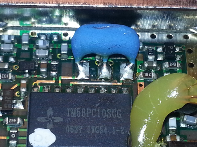
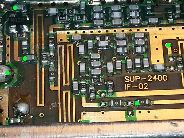
We’ll start on the input section of the board. Remember red dots or lines are parts to be removed.
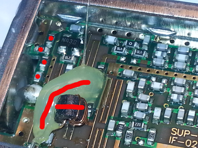
After you have removed those there is a capacitor under all that glue that needs to be removed. Also, in the lower right you’ll notice a red dot on a resistor. Go ahead and get it off there too.
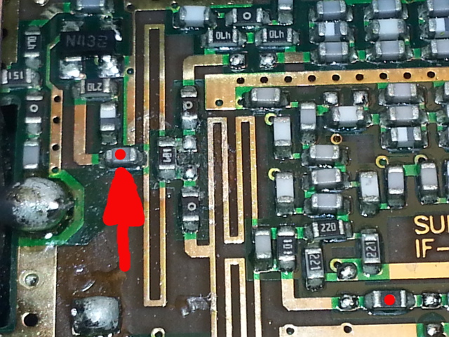
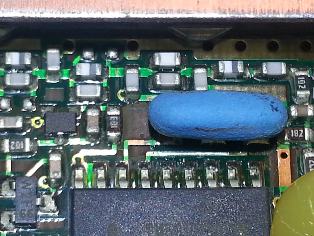
In the next picture you need to cut the trace where the red line is marked. You could cut it between the solder blob and the 101 marked resistor if you like, just to avoid cutting the hole trace that we’ll soon need. I’ve found that if I scrape across there with the tip of an exacto knife it goes a lot easier, even rolling the sharp edge up and applying plenty of pressure. The red dot in the lower left is the same as the one in the lower right in the previous picture, just to avoid confusion. The red dot in the upper right can be removed now too or wait until the step after this.
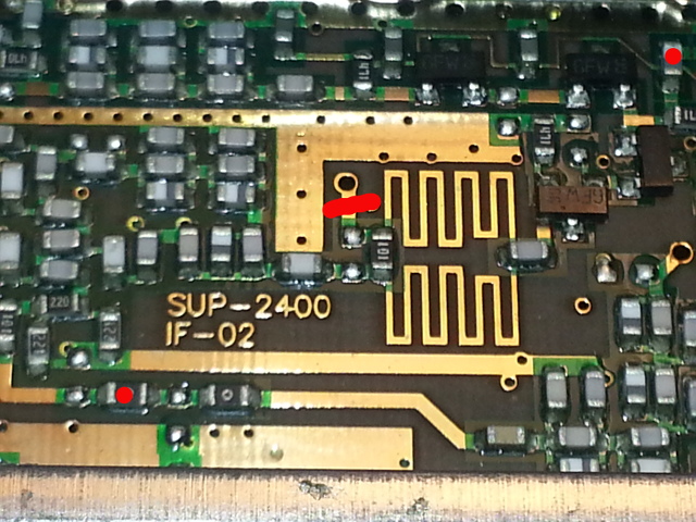
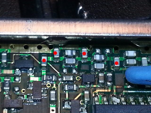
There are four parts marked for removal in this image, including the one mentioned in the previous step.
CAUTION FRAGILE
TAKE GREAT CARE IN THE FOLLOWING STEP:
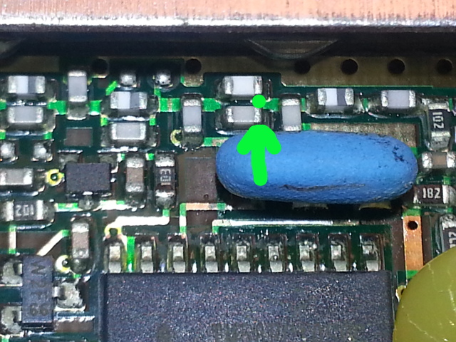
In this step you must VERY GENTLY bend the ceramic oscillator into an upright or leaning towards the IC position. The leads on this device are extremely fragile and it takes some force to bend it into an upright or forward leaning position. Take a small screwdriver or other tool, slide the tip in between the oscillator and the case, and gently apply pressure until it is in a position where you can use a finger tip to move it the rest of the way. It doesn’t need to be bent all the way over, just enough to where you can safely reach your soldering iron tip to the board. If you move it around very much the oscillator WILL separate from the leads, so just get it into position and don’t fool with it any more. We’ll be coming back to this area in a future step. The first picture below is as it appears before adjusting the position.
And this is how it should appear after adjustment:
You’ve made it this far hopefully, now we begin wiring everything back up. For this part we’ll need a small piece of magnet wire or similar about 12 inches (305mm) long. Cut it into pieces at the following lengths – leaving a little extra length on each for screw ups or mismeasurements. Two pieces at 2-1/2 inches (64mm) each, two pieces at 1-1/2 inches (39mm), two pieces at about 1-1/4 inch (32mm).
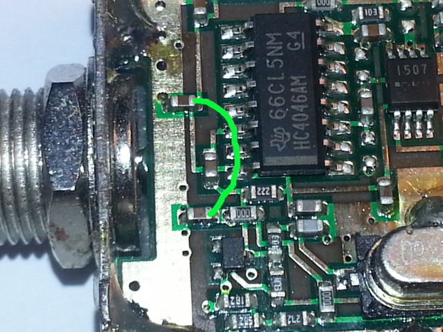
If using magnet wire or any similar type that has a hard (painted on) coating, grab your exacto knife or whatever is handy and scrape about 1/16th inch (or 3-4mm) back on each end to expose the copper for soldering. Take your 1-1/4 inch (32mm) piece of wire and on one end strip back approx 1/2 inch (13mm). Don’t bother with the other end., we’re using it as a handle/prop. Once you have that ready make sure your soldering iron is clean, get your solder and tweezers ready, and continue to the next step. From here on out, areas marked with GREEN DOTS are where we will solder. GREEN LINES are the wire jumpers we are adding.
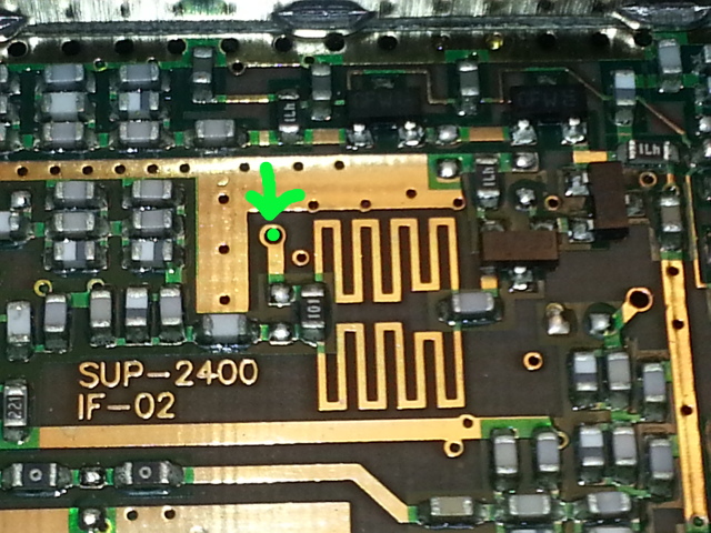
In the following image the green dot indicates where you will place the 1 1/4 inch (32mm) piece of wire. You will slide it into the hole so that only the exposed copper is sticking out above the hole. If you have the converter laying flat about 1/4 inch of wire will stick up through the hole. If not, cut the wire shorter from the other end or slightly bend the wire to where it will stay put. Place a small amount of solder where the wire meets the board, taking care not to use too much solder or form an unwanted solder bridge to the adjacent ground plane. We’re using this kick-stand technique because three other wires must be soldered here and it is very easy to bridge the solder or have the wires jump back up on you while adding the next. This makes it SO much easier, trust me. Once soldered into place flip the board over and apply a small amount of solder where the wire meets the board and trim the excess
This is the backside where you will solder and trim the excess. Once done flip the board back over and continue to the next step.
This image shows the beginning locations of where we are soldering from and too. Don’t solder anything yet:
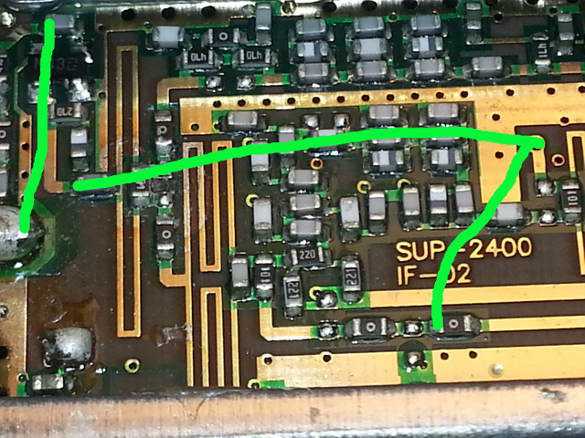
This next image shows the first three jumpers connecting the previously mentioned points. First take your 1-1/2 inch (39mm) wire and solder one side to the RF input, which is the big blob of solder middle far left. The solder that is there is nasty to get started so tin your iron tip a little to help the heat transfer fast. This is the most difficult part of the whole mod, solder (very little here) the other end of that wire to the capacitor marked in green in the far top left corner – solder it to the left side. Be very careful here as it is SO easy to create a solder bridge. If you have a solder sucker or solder braid you might keep it handy here. The wire should loop up a little bit once you’re done there.
The next wire to solder is 2-1/2 inches (64mm) and starts at the left pad where I marked the capacitor for removal earlier. (The next green dot to the right of the RF input). Apply a small amount of solder to the pad, and place the wire before removing the iron. Stretch the wire out so it touches the kickstand wire. If it is way too long you can trim it some but remember to strip your wire back again. Don’t solder it to the kickstand yet.
The final wire for this step begins at the bottom center green dot and you’ll use the remaining 1-1/2 inch (39mm) wire. Solder one end to the bottom green dot and stretch the wire so it touches the kickstand wire.
In this step we’ll attach the remaining 2-1/2 inch (64mm) wire and solder it and the other two wires to the kickstand. Be careful in behind the ceramic oscillator! This pic just shows the solder point behind the oscillator, the following picture shows this wire feeding back to the kickstand for soldering.
And the wire link:
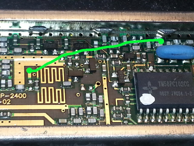
Make sure to trim and scrape as necessary then solder all three wires to the kickstand – above board level so as not to bugger up the board or bridge to ground. Now is an excellent time to get your magnifying glass or goggles out and have a good look everywhere your soldering iron got near. Little solder balls can normally be popped loose with your exacto knife, but if necessary use the soldering iron and solder sucker or braid. Make sure you don’t have any bridges to ground or other unintended traces. Only one more wire to go.
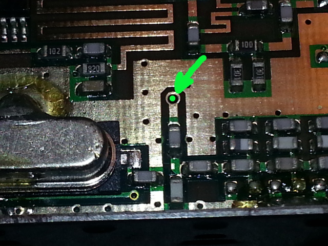
Flip the board over and solder the remaining 1-1/4 inch (32mm) wire as shown in the image below. This insures voltage gets to the PLL.
You’ll need a bias tee that can provide 7-12v or so and feed from the SDR side (the side with the glued on cable). Make sure to hook your SDR or other radio to the correct side of the bias tee. You could fry your device, No fun!
Well, if you were able to stomach my rambling and you made it this far, Congratulations! You now have a microwave downconverter capable of up to 4.5GHz with an RTL-SDR dongle for much less than an expensive SDR. I make no claims on performance but it should be pretty decent considering the costs involved. Remember you’ll probably need an LNA for many purposes in the microwave bands due to the low power nature of the services and the distances involved.
I hope this was helpful to you, if you have any questions I’ll try to answer them in the comments below, on reddit, email, or whatever. I have 3 or 4 more of these laying here if someone needs one and isn’t comfortable doing the mod themselves. Work out a trade or something. If you found this tutorial helpful leave a comment.
73’s Chris – KD0CQ

Your articles are great. Licensed for 57 years. Eyesight is failing so wonder if you have an extra fully modified converter by Direct TV. Nothing to trade ut will pay you for your work. I am interested in S Band reception of deep space/lunar landers, rover and future USA return to the moon. Thanks so much for what you do.
Don – W4DF
Hey Don, We can work something out. The cost of one from ebay and est. shipping to you is fine. After some more testing I’m going to recommend you buy or build a High Pass filter somewhere above the UHF TV band (900 – 1000MHZ would be a good spot since your rtlsdr will work great on its own there). TV signals have been swamping me here in the middle of the L-Band. Puts the IF down in the 480-860MHz TV band. Depending on how high you are looking to receive you may want to do some additional mixing before or after the downconverter to bring the IF down some more (easy enough). Some of the deep space stuff is around 6-8GHz. Otherwise it should do the job, assuming you have a big ugly dish to help on the antenna side of things for deep space (9-10ft dish – old C-band sat TV style).
3 questions;
1.What is the frequency offset/shift I need to use in software like sdr sharp to display the correct frequency?
2.What will I be able to get using this without the mod?
3. Can this be used for transmitting?
@JC
1. If working with frequencies above 2400MHz, enter 2,400,000,000. Frequencies below that you’ll need to just do the math in your head and remember that tuning is in reverse. Tune down to go up, and up to tune down. Upside-Down mixing below 2400MHz.
2. Unmodified the Sup-2400 upconverts 250-750 MHz to 1650-2150 MHz. Not very useful for our general purposes unmodified.
3. Likely. A mixer is a mixer after all. BUT it may need further modification. (Something I’ll look at later if there is enough interest). Also filtering is something to be considered both internally and after the unit. You’d need to add amplification after the mixer stage and I would begin testing at less than -20-30dB or lower input power just to be safe.You may hit a few brick walls along the way. I’ve not tried it yet and I would want to comb through the circuit pretty well and clean up any loose ends. Your external RF connections would be reversed. I have enough of them here I may try it later this week and make another post.
Where do wires go for the external power?
@W4RD
Normally you use a Bias-Tee (aka power injector) to power it. But you could add other external power by soldering connections to the LM7805 power regulator. I feed mine with a 13.8v (fed from a bench power supply) homemade bias tee.
7805 pinout: From left to right Pin 1 is input (7-13.8 is enough to drive it. 9v battery would work for a time) Pin 2 (center pin is ground) and Pin 3 is output to the circuit, leave it alone.
https://www.fairchildsemi.com/datasheets/LM/LM7805.pdf
@kd0cq
Thanks, I’ve received mine from the USA the other day, it did take about 4 weeks to come. I’m going to play around with it in the weekend. I’ve got some kanthal wire, which I used for chipping ps3 years back, that should be ok instead of magnet wire shouldn’t it?
@W4RD
That should be fine, as long as its resistance isn’t too high. One thing to consider is keeping it from grounding out against the case etc if it doesn’t have any type of insulation.
I actually found some bias-T’s at a thrift shop for 50 cents. The kind made by direct tv and say something about dc bias and 2150mhz on them. I hooked up a power supply and clamped the ground to the case and shoved the positive end’s wire in the appropriate antenna connector hole. At first I thought the 2150mhz upper rating might be a problem, but then remembered that the up/down converter outputs at a lower frequency. I think the major difference is I have it hooked up backwards compared to it’s intended use with these devices as it was meant to split powered satellite coax off of UHF TV, now it’s splitting the power off from the rtl-sdr and only to the converter. (note i haven’t actually done the mod yet to know how well this works or not)
Dr op KD0CQ,
I’m very intetested in this mod.So in this downconverter. Is there still one you can send me?
73 de DE8MSH
Marco
I am building a prototype for a project and think I need a more sensitive HackRF One that is Rx *only* from 4GHz -5GHz. I tried using the HackRF One for sensitive measurements around the 5GHz band and was unable to discern any measurable signal with/without the EMI kit and conducted the same tests with another HackRF One user and we arrived at same conclusion. The Rx sensitivity rolls off around 3GHz. I tried a low noise amplifier in attempt make any signal stand out to no avail.
A HackRF user recommended a downconverter. That is what I am looking for at the moment.
Do you have any suggestions or advice?
Thanks,
John
Would you happen to know if there is a PCB & hardware difference between the Rev2 and Rev3 SUP-2400? As far as I can tell from looking online it seems to be a different color of plastic, but I can’t seem to really get a solid answer.
73 – KC2OYX
Hi,
Is there a reason why it’s recommended to use Magnet Wire do to the patch ? Less loss in magnet wire ?
Thanks for the tutorial, really cool stuff!
Etienne
I reckon you could use what ever is available, but you need to remember you’re soldering it to very tiny points on the board, so smaller the better.. I’ve got magnet wire on hand so I just went with it.
very cool. any chance you can provide before and after schematics?
Working on another project right now, when I get through that in a few days I’ll see about putting one together.
I want to be able to view the 2.4ghz waterfall of wifi, Bluetooth, rc radio tx, etc. with my rtl stick.
I’m somewhat confident that I can do the soldering and de-soldering but can you explain more on the “bias tee” part? I’m just now learning about them.
And how would everything connect together? (antenna>downconverter>rtl stick>USB port?)
Do you have any pre-made ones for sale?
Thank you Chris for the fascinating work. Is there a specific LNA & Bias Tee that is compatible with the 100khz-1.7Ghz SDR that you are using ? Thank you. ?
Hey! Thanks for the great mod-guide! It still seems a little sketchy to me in regard to the power-feed to the sup-2400 unit? Is +5 VDC really enough to properly drive it? I’m considering using it together with my Airspy, as it already has a built in bias-t option available…
The system runs on 5VDC via the LM7805 voltage regulator. I don’t think the voltage from your Airspy will give it enough to run properly through the regulator. However, if you take the regulator out of the picture then yes, you should be able to run it just fine. There are a limited amount of active devices with the regulator out of the way so the current draw may be sufficient.
I’ve got an Airspy mini. If I get time this weekend I’ll bypass the regulator and see how well it works.Since I got my HackRF I haven’t paid much attention to the sup2400, but the Airspy+downconverter should be an order of magnitude better on the RX side of things than the 8 bit HackRF or RTLSDR.
Too many projects and not enough time.
Hi: Thanks for the mod, ordered a unit, looking forward to sniffing 2.4g on my SDR!
Do you have the before/after schematics? I like to attempt to understand what I’m doing . . . Thanks, John KD9BSD
I’m hoping maybe you could help me out if one doesn’t want to use a bias tee can you maybe show what inductor to remove and the best place to tap the plus hot wire. I would greatly appreciate it.
Hi,
I received your mod from your shop (thx for making this available!).
But when I want to check on 2.4Ghz (for wifi or bluetooth), I don’t see any changes.
I’m simply using a 820T2 rtl-sdr with your device, and sdrsharp. Of course I shifted frequency setting. Antenna is omnidirectional 9db from a hamradio shop.
Do I need to add hardware in the setup to make it work (filter ??), please?
If so, do you have some part number for reference?
As I see in videos you’re able to sense this band, I would love to do the same.
Thx for your help 🙂
Regards,
Excellent job! I don’t understand where to connect power supply. 🙁 Could you advice me, please? Thank you!
Has anyone tried changing the 9.375mhz LO crystal to a slightly lower value so as to lower the 2400mhz LO frequency to make the downconverter better suited for use as a simple wi-fi spectrum analyser when coupled with SDR. As it stands the 2400mhz oscilator makes it tricky for frequencies around 2400 ie 2385-2415mhz. In theory an 8.912mhz xtal should give a LO frequency of 2281.4.
im not good at all with micro soldering like this ,
is it possible just to canibalize the crystal along with few other parts and
piece them together for a better circuit instead of this
im not good at all with micro soldering like this ,
is it possible just to canibalize the crystal along with few other parts and
piece them together for a better circuit instead of this
It’s possible but why would you do that when DirecTV’s done 95% of the work for you. By the time that you desolder all the chips and resistors that matter it’s going to be more work and a lot of these are actually needed.
So I was just getting ready to do the tricky solder from the RF input to the capacitor in the far top left corner and I realized that 1: that whole section you are soldering to to the left of the capacitor is grounded to the case so you can connect that wire anywhere on the case or rail ( and thus making it a lot easier) and electrically should be identical and 2: that seems to me that that would be creating a short between the inner coax and the outer coax ground. Am I soldering to the wrong spot or is it indeed fine to have that shorted?
Great hack! Is it possible to simplify, or improve, if i ONLY need to receive Bluetooth? Thx!
These modified available for 2.2 – 2.4 . Gotta to have some to monitor the Chinese lunar lander/rover ….help
Can we apply same mod to zinwell SUP 2400?
What’s up everyone, it’s my first visit at this web page, and piece of writing
is really fruitful in support of me, keep up posting
these articles or reviews.
The best in class, Depoxito provide you high-end experience that
attend to the see and environment of genuine
VIP standarts, we provide you the best attractive to high-level experience of VIPs expect in any summit
end casino, grand live casino royale come up with the
money for you the extra studio design element including the grand blackjack, offering our VIP Customer the
best experience of a Salon privee table.
New style table as well as feature across the room once grand roulette upgraded on our provider
playtechs mini prestige roulette which delivering more interesting and richer playing experience.
The extra experience contains a sum of seven tables including five blackjack tables, one roulette table and one baccarat
table. Grand stimulate casino royale has been high hand-engineered to fit the needs of our customer to using it, and contains unique
elements that is specially designed to maximize the impact value we got from our customers and diversify it to the existing network.
Soon, Depoxito will fabricate an bigger authenticity technology
on conscious casino for our VIP member, these most advocate technology ever seen in bring to life casino including this bigger reality.
Which permit players to experience products upon an entire new level which is never seen previously literally leaping
out of the game and taking the blackjack, baccarat,
roulette and further game into the gather
together entire level.
Depoxito VIP Baccarat, we offer you the extremely exclusive living VIP Baccarat that
is played next happening to 7 players at the similar table
and our deeply trained lovely living baccarat dealer.
And of course our VIP aficionado will feel as if they were in fact sitting at one of the summit
casino baccarat table. This immersive gaming experience creates
a hugely thrill-seeking ventilate that our VIP players will locate hard to surpass.
Here is the list of sentient casino game that depoxito provide, we give the widest range of alive casino
games upon the spread around including : blackjack unlimited, blackjack prestige, roulette, baccarat, poker,
hi-lo, sic bo, and grand conscious casino royale such as Grand Baccarat,
Grand Blackjack and Grand Roulette for our VIP member.
And of course as a believer of Depoxito you can enjoy every
the games that we give to you, every you craving
to realize is just visit our site depoxito and register it single-handedly takes stirring to 3 minutes and
later youre pleasing to pretense any game that you want.
Be our VIP, physical our VIP believer of course approved you the best serve you can get from us all you obsession to be
a VIP aficionada is categorically easy. every you obsession is
just save playing upon our site, accumulation and be active
once a VIP considering the amount that our company had
written, save playing and our customer help will
edit you that you are promoted to become a VIP aficionada upon our site.
Aw, this was a really nice post. Finding the time and actual
effort to generate a great article… but what can I
say… I put things off a lot and don’t seem to get anything done.
Ubobet is an internationally trusted gambling dealer before 2001 until now.
By holding ascribed right of entry for online gambling sites that provide various types of betting games.
Games genial include Sportsbook, live Casino and Cockfight.
Ubobet has reached the entire world gambling shout from the rooftops including the Indonesian market.
At present, every daylight there are more than 100 thousand players who entrust their bets in the city of Ubobet.
Ubobet List Site
To register an account, players cannot complete it directly on the Ubobet
site. In additional words, prospective players must register through
the attributed agent site for Ubobet listings such as Pandora188.
By using Pandora188 ID the performer can bet on this city.
How to register is quite easy, just by filling out the registration form correctly.
After that make a addition of at least 25 thousand,
later the artiste can bet upon Ubobet. all artist who joins as a
believer at Pandora188 is entitled to a freebet added
and as well as a daily addition extra without exception.
Ubobet Login
After registering, players can log in upon Ubobet
in two ways. The first is through official cronies who have collaborations such as Pandora188.
Because the two sites have already formed a partnership, which means that betting on the Pandora188 site is the thesame as betting on Ubobet directly.
Or by the second mannerism you can directly log in to the Ubobet site
if you already have an account. How to log in Ubobet
is quite easy, just enter your ID & password correctly.
A great article provides the right information. And a Fantastic hack! Is it conceivable to facilitate? Thanks for such amazing article!
Do you have before and after block or circuit diagrams for this awesome mod?
Thanks a lot for the excellent explanation.
It looks like the given wire lengths are about twice the required ones. I assume they were given only as a starting point.
Then the ends have to be scrapped when the actual lengths are known.
How do you receive up to 4,5ghz? Is there a voltage on the bias T that changes the range of the sup-2400?